Vertical Hall Technology Enables Effective Tamper Detection
Various mechanical and electronic systems are potential targets for magnetic tampering. Unscrupulous individuals may attack deployed electronics such as smart meters, ATMs, gambling/gaming machines, ticket machines, or electronic locks, to name a few, hoping to alter or disable them or steal product or service. This article focuses on smart electricity meters, but the principles discussed apply directly to other systems as well.
All over the globe, smart meters are being deployed to make energy usage reporting and monitoring more efficient and accurate. Many water meters, gas meters, and electricity meters contain smart electronics that allow the automated electronic collection and transmission of usage. According to Navigant Research1, there will be 131 million smart electricity meters shipped worldwide annually by 2018. Electrical energy theft is a major problem for grid operators and government regulators. Smart meters are being attacked with magnets in an attempt to trick the meters into reading zero, or substantially reduced, energy usage2. It is estimated that nearly $90B of energy has been stolen each year due to smart meter tampering2.

Figure 1: Typical Smart Electric Meter
One method employed in tampering with electronic meters is using strong magnets to disrupt the meter’s ability to detect power consumption3. The magnets are typically very strong and may be relatively large and heavy. Magnets such as this can be purchased online or simply salvaged from discarded electronics and computers (e-waste). As these magnets are brought in close proximity to the meter, they begin to magnetically saturate the current transformers used to detect the flow of current through the meter. The saturation of the core essentially “blinds” the meter to how much current is flowing through it.
Although it may be challenging to meter manufacturers to prevent this kind of behavior at the point of use, it is quite possible to detect attempts at tampering so that remedial action can be taken such as dispatching service personnel or remotely disabling the meter. Across the globe, there are multiple organizations that are working toward defining smart meter specifications that include the requirement for meters to detect attempted tampering. See “Table 2: Smart Meter Industry Standards” (below) for more details.
To be effective, a magnetic sensor used to detect tampering must have the following features:
- High sensitivity: Even though the magnet applied to the outside of the system may be strong, the magnetic field strength of a magnet decays exponentially as it is moved further away. The field strength at the internal location of the sensor may be much lower than the field at the surface of the magnet. Certain components used in the meter may distort an applied magnetic field, resulting in “shadows” or “holes” in the sensor’s detection area if the sensitivity is not high enough.
- High dynamic range: Some magnetic sensing technologies have upper bounds on magnetic fields. Hall-effect technology has no upper limit on applied magnet fields. Omnipolar sensitivity: It is unlikely that the perpetrators of a tampering attempt will pay much attention to which pole of the magnet is applied to the system’s case or they may simply try them all to find one that is effective. The sensor should detect the magnetic field regardless of the magnet’s orientation.
- Omnidirectional sensitivity: many legacy magnetic sensors are only sensitive to fields in a single direction or plane. Since the external magnet may be applied in any orientation to any exposed point on the meter’s surface (front face, top, bottom, or sides), the sensor should be equally sensitive in all three directions (X, Y, and Z).
In general terms, the field strength of a magnet decays exponentially as it is moved further away from the magnet. As an example, a large (50 mm × 50 mm × 50 mm) rare-earth magnet with a surface magnetic strength of 6000 G (600 mT) will have a magnetic field of approximately 600 G (60 mT) when measured 50 mm away (one times the thickness). Figure 2 illustrates this phenomenon. A smaller magnet will have less “reach” than a larger magnet. As a rule of thumb, approximately 1/10th of the magnet field at the surface will be present at a distance equivalent to the thickness of the magnet.

Figure 2: Magnetic Field vs. Distance from Magnetic Pole (mm) 50 mm × 50 mm × 50 mm N45 magnet
When a sensor is installed inside an electricity meter, the distance from the sides and surface of the meter must be taken into account when determining how sensitive the sensor will be to a magnet placed outside the meter anywhere on its surface.
The most popular legacy solution for magnetic sensing has been the Hall-effect sensor IC. These ICs detect magnetic fields using the Hall effect, named after Edwin Hall, who in 1879 discovered that a voltage potential develops across a current-carrying conductive plate when a magnetic field passes through the plate in a direction perpendicular to the plane of the plate4. As shown in Figure 3, a current is applied to a conductive plate. A magnetic field perpendicular to the plate (current flow) will cause a differential voltage to be developed across the plate. The sensor measures this voltage as an indication of the applied field. Note that a traditional planar Hall-effect sensor can only measure magnetic fields perpendicular to the sensing plate or surface. In the case of surface-mount ICs, the plate is usually parallel to the plane of the PCB on which the sensor is mounted. Only fields in the Z dimension are effectively sensed regardless of the orientation/ rotation of the sensor.
Effectively sensing X and Y fields would require additional sensors mounted on separate PCBs at right angles to each other and to the motherboard or leaded sensors installed and possibly lead-formed such that the Hall plates are oriented correctly. Both of the approaches drive up component count and cost, system complexity, and assembly cost. It may be possible to install a large number of traditional planar Hall sensors and rely on “fringe” fields to activate them, but, again, this drives up system cost and complexity.
Various magnetoresistive technologies have been used to create magnetic sensor ICs. These sensors usually have a planar response, i.e., they may detect fields in the X-Y plane but have limited response to Z fields. In addition, very high fields can actually cause the sensor to saturate and malfunction (limited dynamic range). Since the expectation is that tampering will be attempted using a large field, this is a significant limitation.

Figure 3: Planar Hall-Effect Sensor
A recent breakthrough in Hall-effect sensing has enabled the creation of omnidirectional magnetic sensor ICs that match all of the requirements for tamper detection. Advances in IC design and fabrication now support the construction of vertical Hall sensors (see Figure 4). The vertical and planar sensors are based on the same physical phenomena but different construction methods:
Planar: Laid out across the width and length of the chip; will only sense Z dimension regardless of orientation
Vertical: Constructed from top to bottom along the depth of the chip; can be oriented to sense X, Y, or other directions
While a planar Hall element is sensitive to field perpendicular to the face of the IC package, a vertical Hall-effect device is sensitive in an axis that is parallel to the die such as the X or Y dimension. Figure 4 shows the construction details of a vertical Hall plate. Two vertical Hall sensors, combined with a planar Hall sensor in a single IC, form a magnetic sensor that can sense fields regardless of direction (X, Y, and Z) and that is immune to high strength fields. In the past, this solution would have required three discrete ICs that required up to 56 mm2 of PCB area. The recently introduced A1266 from Allegro MicroSystems, LLC is an example of such a device (See Figure 5) in a small, surface-mount SOT-23W package requiring just 9 mm2 of PCB. The A1266 also has very high sensitivity (operating point, BOP) so that it can detect tampering attempts over a large area or volume5. A comparison of the available technologies is shown in Table 1.

Figure 4: Vertical Hall-Effect Sensor

Figure 5: A1266 features a 3D omnipolar response ideal for tamper detection
Table 1: Comparison of Available Technologies for Magnetic Sensor ICs
| Technology | Polarity | Directionality (Highest Sensitivity) |
Notes |
|---|---|---|---|
| Planar Hall | Omnipolar | Z only | Most popular legacy approach |
| Vertical Hall | Omnipolar | X, Y, or other in-plane directions | Leading-edge technology for magnetic sensing ICs |
| Magnetoresistance (MR) | Omnipolar | X-Y plane | May invert at high field |
A mapping of the response of different sensors clearly shows the superiority of a high-sensitivity, omnidirectional, omnipolar sensor. The following maps assume a large rectangular meter with face dimensions of up to 290 mm × 165 mm and a 50 mm × 50 mm × 50 mm N45 magnet (see Figure 6 and Figure 7).
The sensor under test is located in the middle of the electricity meter 35 mm below the front face. The magnet is moved across the length and width of the meter’s front face 10 mm above the surface using a robotic mapping station. Figure 8 shows the mapping station set up to map the response of a sensor.
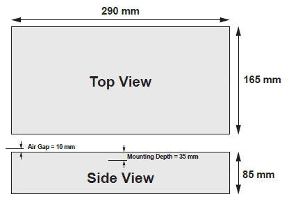
Figure 6: Hypothetical meter dimensions and sensor air gap
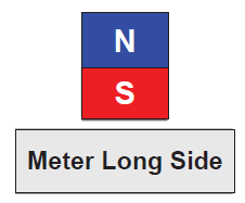
Figure 7: Magnet Orientation (S-pole to face of meter)
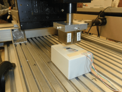
Figure 8: Robotic Mapping Station
Figure 9 shows the results of mapping this hypothetical meter while detecting the magnetic field using a conventional planar Hall sensor having its highest sensitivity in the Z dimension. The area in blue is the region of magnet locations where the sensor under test is able to detect the presence of the magnet. The magnet is easily detected when it is directly above the sensor. As the magnet moves in the X-Y plane, the air gap increases and the field direction may no longer be along the axis of highest sensitivity (Z). Nevertheless, the sensor is able to detect the magnet within a region of approximately 148 mm × 148 mm.
Figure 10 shows the results of mapping the same hypothetical meter while detecting the magnetic field using an omnidirectional (3D) Hall sensor composed of 2 vertical Hall and one planar Hall sensing elements in a single IC package. The area in blue is the region of magnet locations where the sensor under test is able to detect the presence of the magnet. The magnet is easily detected when it is directly above the sensor. As the magnet moves in the X-Y plane, the air gap increases but there is less effect due to the magnet being off-axis. In this case, the sensor can detect the magnet over a much larger area, nearly the entire face of the hypothetical meter (approximately 280 mm × 165 mm of coverage).
In either case, multiple sensors can be used to cover larger areas or volumes. However, fewer instances of the 3D sensor will be needed to cover a large area/volume. In the example shown, the magnet was in the ideal orientation for detection by a conventional planar Hall (1D) sensor. The performance indicated by Figure 9 may degrade in cases where the magnet is applied in other orientations or to the sides of the meter.
This highlights another advantage of the 3D sensor, which is its ability to detect magnetic fields that are randomly applied to the outside of a meter. In the case of a smaller meter, such as a typical single-phase residential electric meter, a single 3D sensor IC may suffice to cover the entire meter. By combining both planar and vertical Hall elements, devices such as the A1266 from Allegro MicroSystems, LLC are able to detect magnetic tampering over a large area/volume and virtually without regard to the orientation of the magnet. This greatly simplifies system design and allows for the most sensitive tamper detection using the fewest number of sensors.
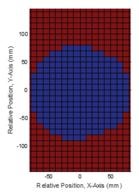
Figure 9: Tamper coverage (43%) with 1D planar Hall-effect sensor (blue denotes detection region)
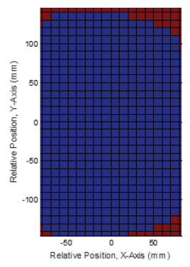
Figure 10: Tamper coverage (92%) with 3D Hall-effect sensor (blue denotes detection region)
Smart Meter Standards
Across the globe, there are multiple organizations that are working toward defining and standardizing smart meter specifications. Increasingly, these standards include a requirement for meters to detect tampering. Some of these organizations are governmental entities while some are ad hoc industry groups. Individual grid operators may also set their own standards for the meters which they procure and deploy. When it comes to magnetic tampering, the level of detail regarding the exact specifications and test methods varies greatly from one standard to another. Table 2 is a list of some of the organizations working towards defining standards for smart grid systems.
Table 2: Smart Meter Industry Standards
| Region | Agency/Standard | Link |
|---|---|---|
| China | CEPRI | www.cepri.com.cn |
| NARI | www.narigroup.com |
|
| SGCC | www.sgcc.com.cn/ywlm/index.shtml |
|
| Germany | DIN | www.din.de/en |
| VDE/FNN | www.vde.com/en/Pages/Homepage.aspx |
|
| India | Bureau of Industry Standards | www.bis.org.in |
| Central Electricity Authority | www.cea.nic.in/regulations.html |
|
| IEEE (India) | smartgrid.ieee.org/resources/public-policy/india |
|
| Ministry of Power | indiasmartgrid.org/en/technology/Pages/Advanced-Metering-Infrastructure.aspx |
|
| Multiple | IEEE – Smartgrids | smartgrid.ieee.org |
| IEC | www.iec.ch/index.htm |
|
| Prime Alliance | www.prime-alliance.org/?p=68 |
|
| U.S.A. | ANSI | www.ansi.org |
| NEMA | www.nema.org |
References
- World Loses $89.3 Billion to Electricity Theft Annually, $58.7 Billion in Emerging Markets, December 9, 2014, PRNewswire (www.prnewswire.com/news-releases/world-loses-893-billion-to-electricity-theft-annually-587-billion-in-emerging-markets-300006515.html), Source: Northeast Group, LLC (www.northeast-group.com)
- FBI: Smart Meter Hacks Likely to Spread, April 9, 2012, Krebs on Security (http://krebsonsecurity.com/2012/04/fbi-smart-meter-hacks-likely-to-spread/)
- Allegro Hall-Effect Sensor ICs, Shaun Milano, Allegro MicroSystems, LLC (https://www.allegromicro.com/en/insights-and-innovations/technical-documents/hall-effect-sensor-ic-publications/allegro-hall-effect-sensor-ics)
- A1266 Micropower Ultrasensitive 3D Hall-Effect Switch datasheet, Allegro MicroSystems, LLC (https://www.allegromicro.com/en/products/sense/switches-and-latches/micropower-switches-latches/a1266)
Originally published in EDN China, January 2016. Reprinted with permission.