The Science of Magnets
Fundamentals of Magnetism

Fig. 1
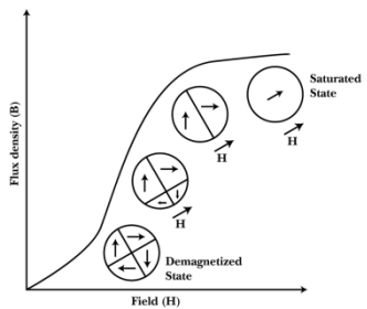
All ferromagnetic materials have atomic magnetic moments that are aligned parallel to each other within small regions called domains. Within these domains, the spontaneous magnetization present is equal to the saturation magnetization of the material, and so the individual domains are fully magnetized at all times. In the absence of an applied field, there is no net magnetic moment or field generated by the material because the magnetization direction of each domain is randomly oriented.
During magnetization of the material, domains whose magnetization directions have a component in the direction of the applied field will grow at the expense of those that do not. Once all of the unfavorably oriented domains have been eliminated by domain wall movement, the magnetization direction of the single domain that remains will be rotated to be parallel to that of the applied field (see figure 1).
Hysteresis Loop

Fig. 2
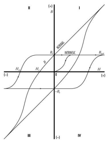
During magnetization, an increasing magnetic field is applied to the material until a saturation point is reached. Upon removing this applied field, a permanent magnet material will not follow the same path down to flux density = 0, instead, it will retain some of its magnetism. The path that the permanent magnet follows is called a hysteresis loop and is a key tool in the quantitative analysis of permanent magnet performance.
These loops are a graphical representation of the relationship between an applied magnetic field and the resulting induced magnetization within a material. The field that is generated by the now magnetized material (Bi) when added to that of the applied field (H) is known as the normal induction (Bn) or simply B. Since this induction has two components, it is defined as:
B = Bi + H
the B vs H curve is known as the normal curve, while the Bi vs H curve is called the intrinsic curve. Examples of these curves, also known as hysteresis loops, are shown in figure 2. The loops show the properties of the magnetic material as it is magnetized and demagnetized. The second quadrant of the loops displays the magnetic properties as the magnet performs work. By comparing the second quadrant to known parameters within a given magnetic circuit, an approximation of the magnetic output can be determined.
When a magnetic field is applied to unmagnitized material, the intrinsic induction (Bi) is established within it, parallel to the applied field. If H is sufficiently strong, the magnet will become fully magnetized at the saturation flux density (Bsat). When the field is reduced to zero, the magnet will recoil to the residual value or remanence (Br), as long as the magnet is within a closed magnetic circuit. Unlike soft magnetic material, the absence of an external magnetic field does not lead to demagnetization.

Fig. 3
One or more air gaps introduced into a magnetic circuit will enable useful work to be performed. The mechanical energy used to separate a magnet from soft iron is stored as potential energy within the air gap and the magnet. This moves the point of operation on the intrinsic curve to the second quadrant. The normal curve in the second quadrant represents the energy output of the magnet and is used during magnet design. If the iron in the circuit is completely removed, the air gap becomes very large and the operating point of the curve now approaches Hc in the second quadrant (known as normal coercivity) and the induction (B) will approach zero.
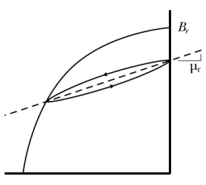
If the air gap is closed again, the stored potential energy is used to perform the work of bringing the magnet and the iron together. The operating point does not, however, return to Br. The magnet recoils along a so-called minor hysteresis loop to a point below Br (figure 3).Repeated opening and closing of the air gap will result in the magnet cycling along this minor hysteresis loop. The average slope of the minor hysteresis loop is the recoil permeability (![]() ).
).
If the demagnetizing field is increased beyond Hc, the operating point of the magnet now moves into the third quadrant of the normal curve. Ultimately, when the intrinsic coercivity (Hci) is reached, the magnet is completely demagnetized. this value is a measure of the magnet's ability to resist demagnetization.
Factors Affecting the Properties of Magnets
Anisotropy in a material is observed when the properties of that material differ depending on its orientation and the direction of testing within the material. In permanent magnets, spontaneous magnetization within domains occurs along certain axes within the material, corresponding to the crystal structure or crystallography of the material. Atomic magnetic moments will align themselves in these directions.
Such orientation is called magnetocrystalline anisotropy and is one of the key factors in the high performance of modern permanent magnets such as NdFeB. When there are no preferred crystallographic directions within a material, then shape anisotropy may arise if there are non-spherical particles present within the material. The long axis of such particles present within the material. The long axis of such particles will be the preferred axis of magnetization. The Alnico family of magnets is an example of a material with this type of anisotropy. The other significant anisotropy relevant to permanent magnets is that which occurs due to stresses acting within the material. When a tensile or compressive stress is applied to a permanent magnet in a particular direction, it will be harder to magnetize the material in that direction.
Magnet geometry is another factor in how difficult it is to magnetize and demagnetize. A magnet with a geometry that causes it to work on a load line below the knee of its second quadrant demagnetization curve will not retain all of the flux that the material is capable of handling, so it will not provide full potential energy to a magnetic circuit. This can be overcome by magnetizing a magnet in its final circuit configuration, i.e. with steel components, or by stacking several magnets together while magnetizing.
In order to reach saturation, a magnet should be exposed to a magnetizing field greater than the sum of its Hci value plus the H value derived from plotting the load line slope from the Br point to the positive H axis. Stacking magnets increases the load line slope which reduces the magnetizing force required.
In general, magnet materials respond negatively to heat because thermal energy reduces the flux density and the ability of domains to remain aligned. Increased thermal energy increases the disorder present and at a particular temperature, the Curie point, the material will lose its ferromagnetism. Overheating a magnet may cause metallurgical changes to occur; in many magnets the safe operating temperature will be less than the Curie point. The one exception are the ferrites (ceramic magnets), which, due to their chemical nature, can withstand temperatures significantly past their Curie points. The ferrites also exhibit the unusual characteristic of an increased coercivity with temperature. Heat treatments as part of the magnet manufacturing process are precisely calculated to precipitate desired phases and to control metallurgical changes.
Permanent magnet materials are sometimes doped with other elements in order to inhibit domain wall movement. However, this is usually accompanied by a corresponding decrease in the amount of flux produced, since these elements reduce the volume of hard magnetic phases within the material.
Post magnetizing treatments like stabilizing, calibrating and thermal cycling all have the same effect on magnets- they provide external energy to allow weak magnetic domains to reverse. After treatment, the magnet is stable until some greater level of external energy is added to the system. Thermal cycling adds random energy to the magnet, and its effect depends on the magnet's so-called self-demagnetizing field. this field is the result of external flow of magnetic flux from one pole back to the other, as well as flux that returns at sub-surface levels. The self-demagnetizing field is affected primarily by the magnet's geometry.
Stabilizing a magnet is a process that uses a reverse magnetic field to do the same thing as temperature cycling. Both stabilizing and thermal cycling result in 'knocking down' of the magnet by some degree. Calibrating, on the other hand, is the process of reducing the magnitude of the magnetic moment of each component so that all magnets act the same in the magnetic circuit.
In all cases where post-magnetization treatment is desired, the effective load line in the operating magnetic circuit should be considered. If the magnet is cycled thermally by itself without the influence of other associated circuit components, the effect will be different from a temperature cycle in the circuit. If the magnets are to be treated independently of the other components, the operating load lines should be determined and specified so that the treatment takes place under operating conditions.