Integrating Hall-Effect Magnetic Sensing Technology into Modern Household Appliances
With the extensive variety of solutions available for position, speed, and current sensing applications, designers can select optimal technologies and packages to achieve their commercial and engineering goals. There always remain the same critical elements that must be considered, such as cost, distance of travel, resolution, accuracy, reliability, and durability, that inevitably bring together the requirements of the application with the appropriate sensing technology. Of the possible solutions, Hall-effect technology, with its contactless magnetic sensing, provides exceptional value.
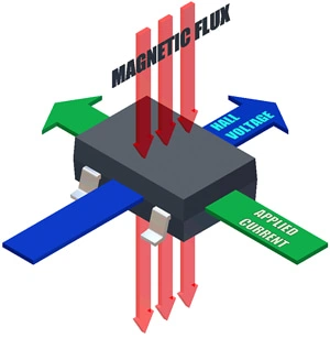
Figure 1. The Hall effect refers to the measurable voltage present when an applied current is influenced by a perpendicular magnetic field.
Introduction
As technology improves, Hall-effect sensor ICs are finding their way into many modern household appliances. The Hall effect refers to the measurable voltage that appears across a conductive material, for example silicon (Si), when an electric current flowing through the conductor is influenced by a magnetic field (see figure 1). Under these conditions a transverse voltage is generated perpendicular to the applied current due to the balancing of the Lorentz and Electromagnetic forces.
Hall-effect sensor ICs have many advantages over traditional mechanical and reed devices. The contactless implementation of Hall sensor ICs improves reliability and durability by virtually eliminating mechanical wear and fatigue. These devices also have the ability to sense magnetic fields that are physically obstructed by nonferrous materials. The small, lightweight package sizes reduce implementation space and mechanical complexity. Many sensor ICs are user programmable to meet custom operational and accuracy requirements.
Background
There are several different types of Hall-effect devices suitable for various applications: Switches, Linears, Speed/Direction ICs, and Current Sensor ICs, to name a few.
Switches and Linears
Switches generate a digital output based on the magnetic operating (BOP) and release (BRP) points of the particular device. Linears generate an analog or pulse width modulated (PWM) output that is directly proportional to the applied magnetic field.
In switch and linear applications, there are several possible magnet configurations for actuating the device. For example, the "head-on" mode of operation refers to moving the magnet perpendicular to the active face of the Hall device, as shown in figure 2.
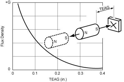
Figure 2. Head-on Hall actuation. TEAG is the total effective air gap.
Alternatively, the "slide-by" mode of operation refers to moving the magnet parallel to the active face of the Hall device (see figure 3). The slide-by method typically results in better sensing precision than the head-on method due to its smaller magnet travel. The large magnetic slope between the poles makes it possible to obtain very precise switch point locations. However, the slide-by method also requires the use of strong magnets and a small total effective air gap (TEAG).
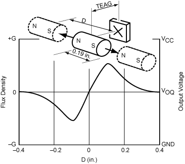
Figure 3. Slide-by actuation. TEAG is the total effective air gap.
Another method for actuating a Hall device is known as vane interrupter switching. A vane is a ferromagnetic material that has a unique configuration of notches cut into it. The vane can be custom shaped for linear or rotational motion. With vane interrupter switching, a magnet and Hall device are mounted in a stationary position such that the Hall device is forced into the "on" state by the activating magnet. When the ferrous material of the vane passes between the Hall device and activating magnet, the vane forms a magnetic shunt to divert the field away from the Hall device. The vane interrupter technique is frequently used where precision switching is required (see figure 4).
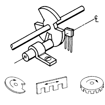
Figure 4. Vane interrupter switching Hall actuation.
Speed and Direction ICs
A variation to vane interrupter switching is to use specialized back-biased Hall-effect devices (see figure 5). Back-biased devices can be used for proximity switching or gear tooth speed and angle sensing. With these devices, a rare-earth pellet and Hall sensor are integrated into a single package, reducing placement and alignment concerns. Back-biased sensor ICs are normally in the "off" state. When a ferrous material passes in front of the package the magnetic field is drawn through the active face of the Hall device, activating the IC.
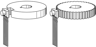
Figure 5. Gear tooth Hall actuation.
Current Sensor ICs
Another use of the Hall effect is to sense current running through a wire or conductor. For small currents up to 20 A, the Hall die and the primary current path can be packaged together in a standard-footprint SOIC-8 surface mount package (see figure 6). The use of flip-chip technology leads to an optimized magnetic coupling between the active face of the Hall element and the field generated by the current to be sensed. This packaging technique eliminates the need for a flux concentrator. The internal resistance of the copper path used for current sensing is typically 1.5 mΩ for low power loss.
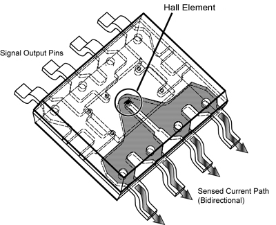
Figure 6. Current sensor Hall device in SOIC-8 package.
For larger currents up to 200 A, the dimensions of the copper conductor must be increased to account for the current density within the material. Because of the magnetic coupling between this thicker conductor and the linear Hall element, a flux concentrator must be used (see figure 7). A typical primary conductor resistance as low as 100 μΩ is achievable.
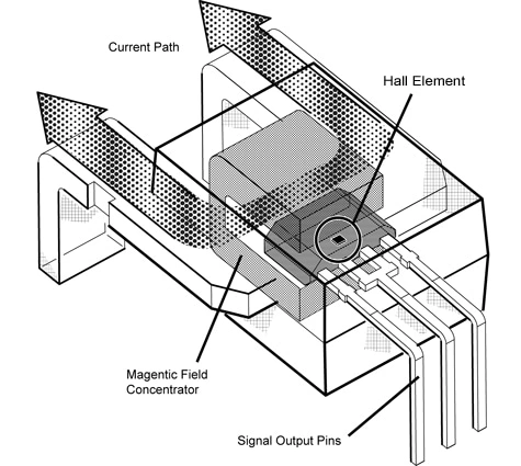
Figure 7. Current sensor IC device for high current (> 200 A) applications.
Hall-effect devices have the primary advantage over other current sensing technologies because the current sensing path is completely electrically isolated from the low voltage signal input/outputs.
Application Examples
Hall technology has been replacing conventional sensing techniques in many applications, including door switches, knob position, drum speed, water level measurement, and motor control. The selection of the appropriate Hall device depends on the level of accuracy and control required. This paper provides a sampling of how Hall technology can be utilized in modern household appliance applications.
Knob Position
Hall sensor ICs provide a contactless solution for determining an appliance’s knob position. Several techniques are available for determining knob location. For example, if the application requires limited, discrete knob positions then simple switches such as the A1120 or A321x can be used. Each switch in the application represents a distinct position mark around the knob. When a magnet that is attached to the turning knob rests above one of the stationary switches, simple electronic logic can decipher which level has been selected.
For higher accuracy applications, a linear device can be used in conjunction with a microprocessor. As the knob turns, the linear device provides the absolute analog position of the knob based on the decay of the magnetic field from the Hall element, while a lookup table in the microprocessor interprets the position of the magnet. The appropriate linear device depends on the desired accuracy in the application. Possibilities include the A132x or programmable A138x.
The different output voltage responses from switch and linear implementations of knob position are shown in figure 8.
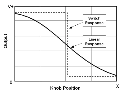
Figure 8. Hall switch versus linear response to knob position.
Fluid Level Detection
Switches and linears can also be used to monitor fluid levels, such as in washing machines or dishwashers. An easy technique for fluid level measurement is to use multiple Hall switches in conjunction with a magnet that is suspended in a float. As the float rises within a tube, it triggers discrete switches that are positioned outside of the tube housing, digitally indicating the water level (see figure 9). The A1120 would be an appropriate switch for this application.
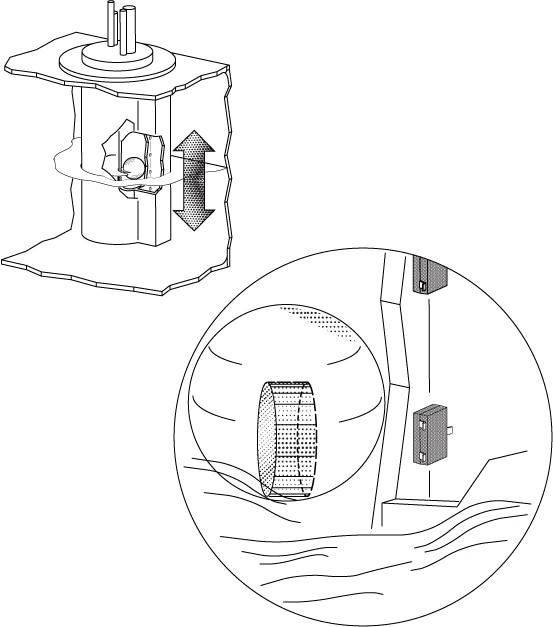
Figure 9. Fluid level sensing technique using magnetic float and switch.
Hall technology can also be used to modify, rather than replace, traditional fluid level measurement techniques. For example, one approach currently used to determine when a drum is full is to expand a plastic diaphragm that pushes against a mechanical switch. An alternative to the mechanical switch assembly would be to implant a magnet into the diaphragm and suspend a Hall switch above it in a head-on configuration (see figure 10). Instead of a using switch, a higher resolution measurement can be achieved by using a linear. The linear solution will determine the absolute water level in the tank instead of merely indicating when the tank is full. Depending on the desired accuracy, a surface mount linear such as the A132x or programmable A138x would be suitable. In these applications, Hall has the advantage of reliability, durability, simplicity, size and weight when compared to mechanical cam based switches.
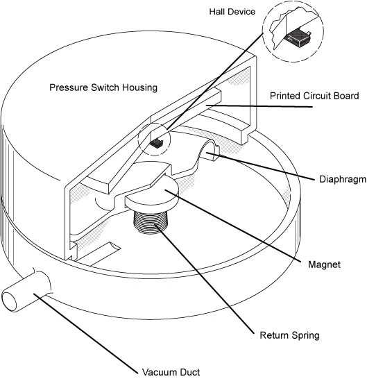
Figure 10. Fluid level sensing technique using inflatable diaphragm implementation.
Drum Rotation Detection
Hall sensor ICs are useful for a variety of drum rotation sensing needs, such as speed, direction, and broken belt detection.
A simple rotation indicator can be constructed by attaching a magnet to a spinning drum and using a stationary Hall switch. Each time the drum makes a full rotation the switch will send out a digital pulse. This signal can be used to simply indicate if the drum is spinning or can also be used by a microprocessor to calculate speed. If higher drum position accuracy is required, the angular position of the drum can be sensed using a differential Hall design, such as the A3425, in conjunction with a gear configuration as shown in figure 5. More sophisticated back-biased Hall configurations, such as the A3423, are capable of providing drum speed information and direction detection.
In addition to sensing the position, speed and direction of a rotating drum, broken belt faults are also useful to detect. For example, if the heating element in a dryer fails to turn off when the dryer belt breaks, the lack of rotation can cause the clothing to catch on fire. Figure 11 shows a possible broken belt detection circuit that works using a magnet attached to a spinning drum and a stationary Hall switch. In this circuit, the central node charges at a rate determined by the R1C1 pair. When a magnet passes by the Hall switch, the IC VOUT signal undergoes a high-low-high transition. The rising edge of the VOUT signal temporarily turns on transistor Q1, discharging the central node. A broken belt will stop the drum from rotating, preventing the rising edge transition from occurring. This allows the central node to charge freely. When the central node reaches a voltage that turns on the Darlington pair, the circuit output switches to a digital low signal, indicating a broken belt fault.
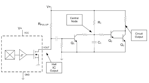
Figure 11. Broken belt detection circuit using simple Hall switch.
Motor Control
Hall-effect current sensor ICs are a robust and simple means of monitoring motor currents for both control and protection. Motor current consumption is directly proportional to the torque the motor exerts. Therefore, a typical method of controlling the speed and applied force of a motor is to feed back its current consumption measurement into a microprocessor. The microprocessor can then calculate whether more or less current must be applied to the motor in order to achieve the desired speed. Hall-effect current sensor ICs can be placed directly in series with the motor (or any inductive load) because they have a very low resistance copper leadframe.
Traditional techniques sense motor current using a shunt placed in the ground switch of a motor control assembly. With this approach, only half of the motor current can be monitored, which decreases accuracy and increases I2R losses. Hall-effect current sensor ICs have input supplies completely isolated from the current path, allowing for high accuracy and low power measurements. Allegro’s ACS712 is available in an SOIC-8 package for use with small nominal currents, and the ACS75x is in a CB package for larger current sensing needs.
Micro-Power Solutions
As society continues to develop its understanding of environmental issues, the demand for low energy appliances grows stronger. The requirements of the US federal government’s Energy Star program are becoming more and more stringent each year. Allegro MicroSystems is the first to offer micro-power Hall switches and linears to help manufacturers minimize their appliance energy consumption.
The 321x family of switches uses a unique clocking scheme and 2.75 V nominal operating voltage to achieve a typical 15 μW of power consumption. The 139x family of linear Hall devices has a 3 V nominal operating voltage with 10 mW of power consumption in the active mode. The 139x devices also have a sleep pin that allows a microcontroller to disable the device, reducing power consumption to a nominal 75 μW (see figure 12). Additionally, when the 139X device is in sleep mode the output of the device transitions to a high impedance state. Therefore, multiple 139X linear Hall sensor ICs can be connected to a single analog-to-digital converter input as long as a polling scheme is used to monitor the output of a single A139X device at any point in time.
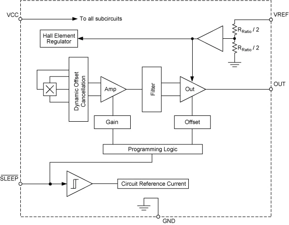
Figure 12. diagram of the 3 V, A139x micro-power linear with sleep pin input.
Conclusion
The applications described in this article are just a few examples of how Hall technology improves the performance and reliability of modern appliances over traditional implementation techniques. Additional Hall applications are summarized in table 1. The appropriate Hall device for a given application can be found using the Allegro Selection Guides.
|
Table 1: Modern Appliance Applications for Hall-Effect Devices
|
||
|---|---|---|
|
Appliance
|
Application
|
Hall Device Type Options
|
|
Washer
|
Lid/door open/closed
|
Switch
|
|
Motor current
|
Linear; integrated current sensor IC
|
|
|
Drum speed/direction
|
Gear tooth; proximity; switch
|
|
|
Out of balance
|
Linear; switch
|
|
|
Water level
|
Linear; switch
|
|
|
Cycle control dial
|
Linear; switch
|
|
|
Flow meter
|
Latches; bipolar switches; linear
|
|
|
Dryer
|
Lid/door open/closed
|
Switch
|
|
Motor current
|
Linear; integrated current sensor IC
|
|
|
Drum speed
|
Gear tooth; proximity; switch
|
|
|
Broken belt
|
Switch; integrated current sensor IC
|
|
|
Cycle control dial
|
Linear; switch
|
|
|
Oven
|
Door oven light
|
Switch
|
|
Self-cleaning door lock/interlock
|
Switch
|
|
|
Refrigerator
|
Ice maker full
|
Latch; switch
|
|
Door light
|
Switch
|
|
|
Motor current
|
Linear; integrated current sensor IC
|
|
|
Shelf position
|
Linear; switch
|
|
|
Dishwasher
|
Door open/closed
|
Switch
|
|
Motor current
|
Linear; integrated current sensor IC
|
|
|
Sprayer motion
|
Gear tooth; proximity; switch
|
|
|
Water level
|
Switch; linear
|
|
|
Flow meter
|
Latches; bipolar switches
|
|
|
Vacuum Cleaner
|
Motor current
|
Linear; integrated current sensor IC
|
|
VR motor commutation
|
Latch; bipolar switches
|
|
|
On/off
|
Switch
|
|
|
Speed control
|
Linear; switch
|
|
|
Vending Machine
|
Home position
|
Switch
|
|
Pulse count/encoder
|
Latch; bipolar switch
|
|
|
Selection switch
|
Switch
|
|
|
Garage Door Opener
|
End stop positions
|
Switch
|
|
Pulse count/encoder
|
Latch; bipolar switch
|
|
|
Motor current
|
Linear; integrated current sensor IC
|
|
|
Blender
|
Speed control
|
Linear; switch
|
|
Water Softener
|
Valve position
|
Latch; switch; linear
|
References
G. Pepka. "Position and Level Sensing Using Hall Effect Sensing Technology."
Allegro MicroSystems technical paper.
Sensor Review Journal SR27-1, February 2007.
M. Hopkins. "The State of the Art in Hall Effect Technology and Its Implications for Appliance Design and Development."
Allegro MicroSystems technical paper.
IATC, March, 2004.
A. Friedrich, M. Doogue, J. Cummings. "Recent Trends in Hall Effect Current Sensing."
Allegro MicroSystems technical paper.
PCIM 2006, May 2006.
The products described herein are manufactured under one or more of the following U.S. patents: 5,619,137; 5,621,319; 6,781,359; 7,075,287; 7,166,807; 7,265,531; 7,425,821; or other patents pending.
Allegro MicroSystems, LLC reserves the right to make, from time to time, such departures from the detail specifications as may be required to permit improvements in the performance, reliability, or manufacturability of its products. Before placing an order, the user is cautioned to verify that the information being relied upon is current.
Allegro’s products are not to be used in life support devices or systems, if a failure of an Allegro product can reasonably be expected to cause the failure of that life support device or system, or to affect the safety or effectiveness of that device or system.
The information included herein is believed to be accurate and reliable. However, Allegro MicroSystems, LLC assumes no responsibility for its use; nor for any infringement of patents or other rights of third parties which may result from its use.