Please use the form below to contact us with regards any questions you may have. We will endeavour to respond to you as quickly as we can. Please continue to browse the site for any other information in the meantime.
Will will respond as soon as we can. Feel free to browse the rest of this site in the meantime for any further information you may require. Here is a link to our main products page
Table 1. ACS710-12C Noise Level and Current Resolution | ||||
CF | BW | VRMS Noise | VP-P Noise | Current Resolution |
0 | 120 | 1523 | 9138 | 163 |
1 | 94 | 1185 | 7110 | 127 |
2.2 | 43 | 1010 | 6060 | 108 |
4.7 | 20 | 874 | 5244 | 94 |
10 | 9 | 768 | 4608 | 82 |
22 | 4 | 724 | 4344 | 78 |
47 | 2 | 682 | 4092 | 73 |
Table 2. ACS710-25C Noise Level and Current Resolution | ||||
CF | BW | VRMS Noise | VP-P Noise | Current Resolution |
0 | 120 | 994 | 5964 | 213 |
1 | 94 | 948 | 5688 | 203 |
2.2 | 43 | 713 | 4278 | 153 |
4.7 | 20 | 658 | 3948 | 141 |
10 | 9 | 602 | 3612 | 129 |
22 | 4 | 570 | 3420 | 122 |
47 | 2 | 536 | 3216 | 115 |
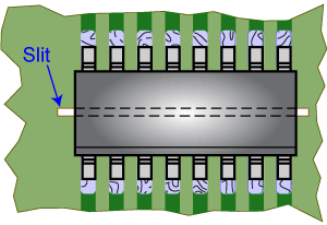
The creepage distance on the surface of the sensor IC package measures approximately: 7.50 + 2.00 = 9.50 (mm)
The creepage distance on the surface of the printed circuit board on which the sensor IC is mounted may be increased, if necessary, by cutting a slit on the board between the solder pads on opposite sides of the sensor IC package. Refer to figure 4.
|
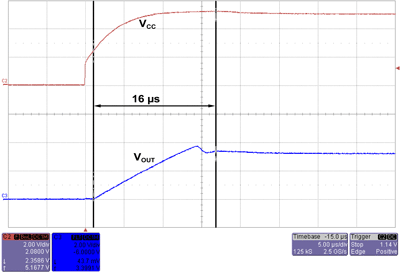
Table 3. ACS710-12C Input Current versus Power-On Time |
|
|
IP |
tPO |
|
0 |
14 |
|
12.5 |
16 |

|
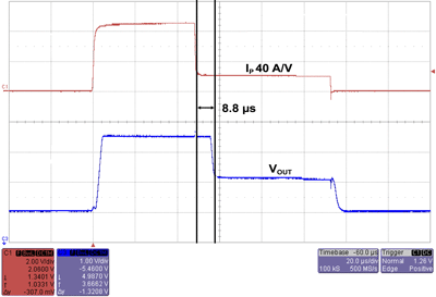
Table 4. Continuous Current Overcurrent Limits |
|
|
tA |
IP(OClim) |
|
25 |
45 |
|
85 |
35 |
|
125 |
25 |
|
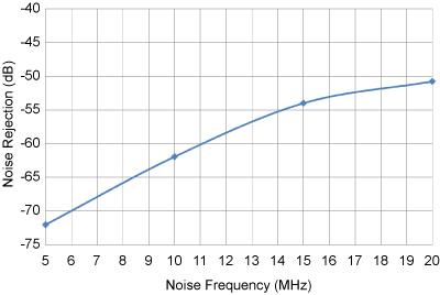
Table 6. Typical Capacitive Coupling of |
||
|
Frequency |
VOUT |
Noise Rejection |
|
5 |
5 |
−72 |
|
10 |
16 |
−62 |
|
15 |
40 |
−54 |
|
20 |
58 |
−51 |