Improving Efficiency in Smart Grid Applications With Fully Integrated Current Sensing ICs
Focus on the Photovoltaic System
With increasing concerns about the global demand for energy and environmental awareness, power electronics applications are under pressure to improve efficiency. The advent of the Smart Grid, Plug-in Hybrid Electric Vehicles (PHEV) and full Battery Electric Vehicles (BEV), as well as grid-tied photovoltaic (PV) and other grid-tied renewable energy systems, all will require development of highefficiency inverters. In particular, new developments in the design of photovoltaic inverters are targeted at minimizing the cost-per-watt and increasing the maximum power harnessed from the solar system to deliver the best possible return on investment. Allegro™ MicroSystems LLC has developed a unique family of high performance integrated current sensor ICs designed to be used in Smart Grid inverter and motor control applications.
PV Systems
The rising cost of fossil fuels, combined with a growing awareness of the need for low carbon emissions, have triggered intense research and development activities in technologies that use renewable resources. Renewable energy contributes 19% of global final consumption and has grown at double-digit rates annually for many technologies over the last five years [1]. In particular, windmills and photovoltaic (PV) solar technologies have been experiencing significant development, with grid-connected solar PV technology growing the fastest at annual rates of greater than 60% [1].
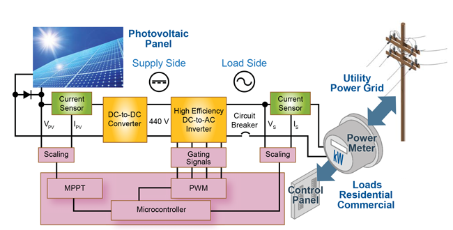
The major challenge associated with solar energy production is the conversion of the DC currents generated by the PV panel to the sinusoidal AC current of the power grid. Figure1 illustrates a simple block diagram of the PV system and is comprised of a solar panel array and an inverter in a grid-connected configuration with switching control as well as maximum power point tracking (MPPT). MPPT modules are often employed on each PV string for larger arrays because the maximum power point can change continually from one solar string to another depending on variances in solar radiation. Current sensors are essential in tracking these DC current levels and a microcontroller is then used to adjust the system’s operating point to deliver the maximum power available from each PV string. A comparison of these current measurements is also useful in detecting deficient PV strings. The vast number of low power PV systems for residential use can also employ current sensors to control MPPT and improve inverter efficiency. MPPT and inverter control both require accurate current sensing.

A Revolution in Hall-Effect Current Sensing
The features and benefits of these industry-leading Allegro current sensor ICs include:
- The highest current resolution, lowest-noise spectral density Hall sensor ICs in the marketplace
- Precise factory programming of sensor IC gain and offset
- Signal processing and package design innovations enable greater than 120 kHz output bandwidth and fast output response time
- Proprietary, small footprint sensor IC packages, with galvanic isolation
- Reduced power loss: through-hole compliant and low-resistance integrated conductor packages
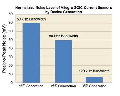
By employing advanced BiCMOS process technology and innovative packaging techniques, it is possible to provide a fully integrated solution with enhanced accuracy and resolution even at high bandwidth. Figure 2 shows the evolution of output peak to peak noise and bandwidth of Allegro Hall current sensor linear ICs. The noise level has seen a reduction of 10X while the bandwidth has more than doubled.
Inverter Sensing
An inverter includes three major parts: a DC-to-DC converter that amplifies the voltage from solar panels to the high voltage required by the grid; a DC-to-AC inverter that converts the DC current into the AC sinusoidal shape of the grid; and various electrical control components to control the system and optimize efficiency as well as ensuring compliance with the requirements of the power regulations and safety standards.
The high efficiency DC-to-AC inverter generates an alternating current signal for direct connection to the AC power grid. As a result, the signal must be compliant with the utility system requirements. It must be synchronized to the grid and have low total harmonic distortion (THD). Electrical current sensors are needed here in a control loop in order to ensure proper connection to the grid. They must accurately measure both AC and DC currents and have high dynamic performances. Very fast response time is required to react quickly to any change in the grid and shut off or disconnect the system before damage occurs. The high output bandwidth feature enables the system to measure highfrequency AC currents and harmonics.
For inverters without a transformer or with a high-frequency transformer, low offset temperature drift (high accuracy) sensors make it possible to control the DC component in the AC current fed to the grid. Regulations differ from country to country for this electrical DC current limit, but generally it is small and of the
order of tens to hundreds of milliamperes. Furthermore, failure functions such as short-circuit protection and overload protection make it easy for the current sensors to detect these conditions and quickly report them to the microcontroller.

Advanced Hall Current Sensor IC Solutions
One drawback of conventional Hall-effect sensors, when used in current sensing applications, has been a general limitation in accuracy of the zero ampere output voltage and Hall amplifier sensitivity over changes in temperature as well as the output signal bandwidth and output noise. Allegro MicroSystems has developed a family of innovative, fully integrated, current sensor packages that are ideally suited for inverter applications that drastically improve the offset, sensitivity and bandwidth operation of Hall based current sensor IC’s. In each of the sensor packages, the IC itself is the most important component and contains a precision Hall-effect element that is coupled to a low-offset, high-accuracy amplifier.
The BiCMOS process allows accurate amplifier design with digital circuitry for factory programming of the gain and offset over temperature. Both the Hall element and the amplifier are chopperstabilized for enhanced accuracy and offset drift performance. Allegro has developed proprietary chopper stabilization and filtering techniques that result in the industry leading, low-noise performance of the Hall IC output signal as shown in figure 2. The analog output response times of less than 4 μs allows sensing of higher frequency switching inverters. In applications that work at lower frequencies the output can be further filtered to lower the noise on the output and improve the resolution. The output resolution of Allegro Hall current sensors has been revolutionized by these improved amplifier and filtering technologies.
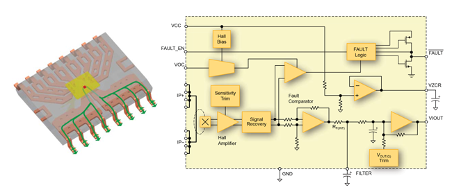
Figure 3 shows a uniquely effective, patented packaging technique for Hall-effect current sensor IC that provides a small form factor, especially useful where space is limited. The current to be sensed flows through the conductive copper path between the four pins at the lower left corner of the package and the four pins at the lower right corner of the package. The Hall-effect IC is assembled into the package using standard flip chip assembly techniques. Three major advantages result:
- The Hall-effect sensing element is in close proximity to the current-carrying conductor, thereby maximizing magnetic coupling and signal to noise ratio that improves device accuracy.
- The Hall-effect IC is not in contact with the integrated conductor, thereby maintaining voltage isolation and enabling working voltages as high as 500 VRMS needed on the DC side of the PV inverter and the DC-to-DC converter. Solder bumps attached to the low-voltage input/output pads on the Hall IC make contact
with the lead fingers shown in the upper portion of figure 3. - Since the Hall-effect current sensor linear IC is fully integrated it allows Allegro to factory program the device to compensate for zero amp and sensitivity variation over temperature.


of a ‘C’ core around a conductor
The block diagram in figure 3 shows that advanced features can be integrated into the device to reduce overall bill of material costs; for example, an overcurrent fault output that responds in < 2 μs with a user-programmable trip point. The fast digital fault output can be used to protect IGBT devices in case of over-current conditions. The internal conductor resistance is only 1 mΩ and provides for low power loss, enabling the package to support up to 40 A of continuous current at 85°C ambient temperature. This device comes in with an analog output, and Allegro part numbers are available with different sensitivities for use in low power inverters.
The Allegro CB package current sensor IC family (figure 4) provides users with an integrated current sensing solution that offers a series conductor resistance of 100 μΩ for ultra-low power loss. These current sensor ICs are designed for sensing currents from 50 to 200 A and can be used in high power PV inverters.
In the CB package configuration, a high-accuracy, high-bandwidth linear Hall IC is placed in the gap of a concentrating, ferromagnetic core that wraps around the primary conductor. These integrated sensors offer a working voltage of approximately 450 VRMS .
For applications that require sensing currents above 200 A, as in HEV inverters or high power PV systems, designers can use an Allegro family of current sensor linear Hall sensor ICs in the gap of a simple steel ‘C’ core concentrator as in figure 5. These sensors come with analog or a digital PWM output.
Conclusion
Allegro MicroSystems has developed a line of fully integrated Hall-effect current sensor ICs that provide highly accurate output voltage signals proportional to the applied current. Advanced IC and packaging techniques enable bandwidth improvements above 120 kHz as well as low noise amplifier designs that improve device accuracy throughout the entire operating temperature range. The proprietary packaging techniques also provide small form factor devices with galvanic isolation and Allegro factory programming for stable zero ampere and full scale output over temperature. These advances allow design engineers to use Hall-effect based current sensor ICs in new applications where increased energy efficiency or new operating features are required.
References
[1] REN21 Renewable Energy Policy Network for the 21st Century – Renewables 2010, Global Status Report – p.15
[2] IMS Research – PV Inverters, Annual report 2010
This paper originally appeared at the Smart Grid Forum in October 2011.