Please use the form below to contact us with regards any questions you may have. We will endeavour to respond to you as quickly as we can. Please continue to browse the site for any other information in the meantime.
Will will respond as soon as we can. Feel free to browse the rest of this site in the meantime for any further information you may require. Here is a link to our main products page

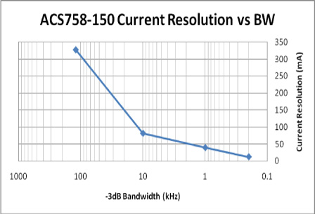
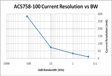
The current resolution of the ACS758 family of current sensor ICs is limited by the noise floor of the device output signal. For example, the ACS758-050 version can resolve a change in current level of about 250 mA, at 25°C, through its primary conductor leads. The 200 A version can resolve approximately 380 mA. At these levels, the amount of magnetic field coupled into the linear Hall-effect IC is just above its noise floor. Resolution can be improved significantly by filtering the output of the ACS758 for applications requiring lower bandwidth. Table 1 lists the noise levels, and hence current resolutions, at various bandwidths. Filtering was accomplished with a simple, first order RC filter. Note the related graphs, figures 2 through 5, which provide a better understanding of the device output resolution that can be achieved through filtering.
|
Table 1. ACS758 Noise Level and Current Resolution versus Bandwidth |
||||
|---|---|---|---|---|
| Device | Bandwidth -3 dB (kHz) |
Noise (mVp-p) |
Current Resolution | |
| (mA) | (% of full scale) | |||
| ACS758-200B | 120 | 3.84 | 384 | 0.192 |
| 10 | 0.92 | 92 | 0.046 | |
| 1 | 0.55 | 55 | 0.028 | |
| 0.2 | 0.15 | 15 | 0.008 | |
| ACS758-150B | 120 | 4.36 | 328 | 0.219 |
| 10 | 1.08 | 81 | 0.046 | |
| 1 | 0.52 | 39 | 0.026 | |
| 0.2 | 0.16 | 12 | 0.008 | |
| ACS758-100B | 120 | 5.69 | 285 | 0.285 |
| 10 | 1.49 | 75 | 0.075 | |
| 1 | 0.67 | 34 | 0.034 | |
| 0.2 | 0.22 | 11 | 0.011 | |
| ACS758-50B | 120 | 10.03 | 251 | 0.502 |
| 10 | 2.95 | 74 | 0.148 | |
| 1 | 1.05 | 26 | 0.053 | |
| 0.2 | 0.43 | 11 | 0.022 | |


|
Table 2. ACS758 Time to Valid Output |
||
|---|---|---|
| IP (A) | 0 | 50 |
| Power-On Time (µs) | 8 | 10 |


|
Table 3. Tested Maximum ACS758 Overcurrent Levels and Durations |
|
|---|---|
| Ambient Temperature (°C) |
Maximum Current (A) |
| 10 s, 10% duty cycle, 100 pulses applied | |
| 25 | 350 |
| 85 | 350 |
| 150 | 260 |
| 3 s, 3% duty cycle, 100 pulses applied | |
| 25 | 450 |
| 85 | 425 |
| 150 | 375 |
| 1 s, 1% duty cycle, 100 pulses applied | |
| 25 | 1200 |
| 85 | 900 |
| 150 | 600 |
|
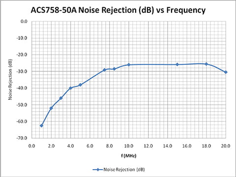
Table 4. Typical Capacitive Coupling of a 20 V Peak-to-Peak Signal on the Current Path |
|||||||||||
|---|---|---|---|---|---|---|---|---|---|---|---|
| f (MHz) | 1.0 | 2.0 | 3.0 | 4.0 | 5.0 | 7.5 | 8.5 | 10.0 | 15.0 | 18.0 | 20.0 |
| VOUT(p-p) (mV) | 15.0 | 50.0 | 100.0 | 200.0 | 250.0 | 700.0 | 750.0 | 1000.0 | 1020.0 | 1050.0 | 600.0 |
| Noise Rejection (dB) | -62.5 | -52.0 | -46.0 | -40.0 | -38.1 | -29.1 | -28.5 | -26.0 | -25.8 | -25.6 | -30.5 |