Sensorless and Always Without Reverse Rotation

Rapid and Accurate Startup for Blower Fan Motors
Abstract
In modern fans or pumps, cost savings and power efficiency incentives are pushing motor designs toward sensorless motor drivers. Conventional motor drivers use trapezoidal motor control with three Hall sensors: The Hall sensors give the rotor position, and the motor generates a robust torque without reverse motion from a starting speed of zero. However, conventional sensorless startup requires rotor alignment, so reverse motion may become associated with this method and torque cannot be generated until the alignment is complete. This article describes how initial rotor position detection techniques can overcome this challenge to provide anti-reverse, fast, sensorless startup.
High-power density motor market trends
Today, the market trend is to use brushless DC (BLDC) motors for their high-power-density motor design. To drive the BLDC motor properly, the precise position of the magnet that is being sensed must be known. This typically requires an angle sensor, such as a magnetic Hall sensor or encoder. Compared to a DC motor, the BLDC solution adds cost and complexity to the controller design. For cost optimization, some BLDC applications may be able to use a controller without a motor angle sensor. This article describes multiple advanced sensorless startup techniques to overcome the challenge of determining the magnet position, as needed for proper BLDC motor startup.
Traditional sensorless startup method
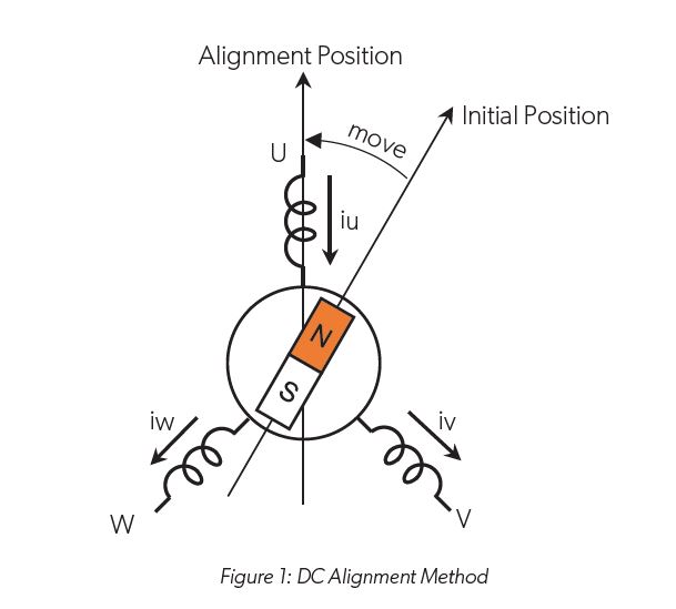
Traditional sensorless drivers use the “DC alignment startup” method, where the controller forces a DC current in the three-phase winding so that the rotor magnet gravitates to the known position. This solution forces the alignment of the current so that the rotor aligns properly with the magnet. This method is shown in Figure 1, with alignment to Phase U. After rotor alignment completes, the motor can begin to rotate from that position.

The DC alignment method is simple, easy, and can be applied to many types of BLDC motors. However, when the motor or connected load has high inertia, the time to settle to the alignment position increases. As a result, overall startup time tends to be longer compared to sensored-BLDC drivers. Also, depending on the parked position of the rotor, the rotor may move backward to align with the stator. This small amount of backward spinning causes an undesirable effect for some applications, such as pumps.
Using this traditional DC alignment method, motor startup—from speed zero to robust, consistent high-inertial spinning—may take more than five seconds.
Conventional IPD startup method: Inductance Saturation
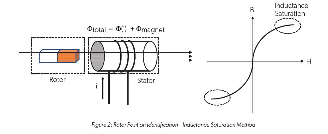
Initial position detection (IPD) methods are available that leverage inductance saturation to enable sensorless detection of the initial rotor position without moving the shaft. Inductance saturation techniques leverage the state of inductance in the stator winding. If the total flux generated by the winding exceeds a certain point, the inductance will become saturated. The stator receives the overall flux generated by the winding and by magnetic flux. The magnetic flux component varies depending on the rotor position, so the inductance saturation current changes with the magnetic flux:
- When the position of the magnet is aligned to the stator, the inductance saturates easily.
- When the magnet is offset 90 degrees from the stator, the saturation effect from the magnet is zero.
Compared to motor startup using the traditional DC alignment method, IPD using inductance saturation is significantly faster: Traditional DC alignment may take more than five seconds and may include reverse rotation, while IPD enables detection of the initial rotor position within, typically, less than 1 ms—without any reverse rotation. IPD using inductance saturation provides initial detection accuracy of 60 degrees. However, this performance comes with an unwanted noise component: Typically, six test current pulses must be injected into the motor, which produces an unwanted click sound six times.

Advanced IPD startup method: Saliency with Inductance Saturation
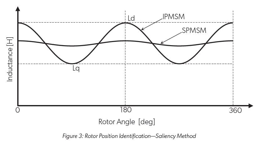
In a permanent magnet synchronous motor (PMSM), the inductance at the motor terminal varies according to the rotor position. This phenomenon, termed “saliency”, is intentionally designed into some PMSMs. For example, depending on application needs, some PMSMs may use an interior permanent magnet synchronous motor (IPMSM) to enhance torque characteristics, while others may use a surface permanent magnet synchronous motor (SPMSM), which has comparatively less saliency. The saliency behavior characterized over the angle —i.e., the inductance difference depending on the rotor position—is depicted in the plot in Figure 3.

Observing inductance can allow the initial position of a rotor to be detected. Because saliency exists regardless of the flux direction from the magnet, saliency characteristics between 0 degrees and 180 degrees are identical to those between 180 degrees and 360 degrees. Thus, use of saliency requires another method, such as the inductance saturation measurement, to identify the north pole or south pole:
- When the magnet (d-axis or inverse d-axis) is aligned to a phase, inductance will be at the maximum.
- When the magnet is offset by 90 degrees (q-axis or inverse q-axis), the inductance will be at the minimum.
One type of IPD technology developed by Allegro MicroSystems leverages the inductance saturation and saliency effects and employs a dedicated analog detection circuit within the motor controller driver. Saliency measurement is achieved using a high-precision comparator. This enables detection of saliency characteristics within six PWM periods, typically. After the saliency measurement is complete, a test current pulse is applied to the winding to check the inductance saturation, which is used to identify the magnetic pole.
This method allows alignment to be ignored, enables detection of the initial position within less than 1 ms without moving the shaft, and provides additional flexibility: If the target motor has low saliency, the initial position can be detected using inductance saturation only. Compared to conventional IPD methods that rely only on inductance saturation, the Allegro IPD method uses a two-stage IPD method, so it reduces the required test pulse currents from six to two, which reduces the number of click sounds. Also, leveraging the saliency effect improves initial detection accuracy from 60 degrees to 30 degrees compared to the conventional IPD method. The Allegro IPD method provides a faster, more accurate, quieter initial detection capability, and leads to fast, reliable, nonreversing startup. An evaluation GUI is available to validate the startup performance.
Conclusion and recommendations
A comparative summary of the BLDC motor startup methods discussed in this article is provided in Table 1. The speed, accuracy, nonreverse, and noise features of the Allegro IPD method make this startup technique ideal for fan blowers for both general and automotive purposes. The available sensorless motor controllers that use the Allegro IPD method include A89301 [1] and A89306 [2] for the general blower fan market, and A89307 [3] for automotive fan blowers. These products drive a motor using a field-oriented control (FOC) system. Driving parameters—including the Allegro IPD method—can be chosen by I2C communication interface and saved into internal NVM, and the motor can spin with preprogrammed parameters.

Originally published by Electronic Design, June 2022. Republished with permission.
Copyright 2022, Allegro MicroSystems.
The information contained in this document does not constitute any representation, warranty, assurance, guaranty, or inducement by Allegro to the customer with respect to the subject matter of this document. The information being provided does not guarantee that a process based on this information will be reliable, or that Allegro has explored all of the possible failure modes. It is the customer’s responsibility to do sufficient qualification testing of the final product to ensure that it is reliable and meets all design requirements.
Copies of this document are considered uncontrolled documents.