Current Sensing For Renewable Energy
In grid-tied photovoltaic systems, designers must focus on minimizing cost per watt to deliver the best possible return on investment
With increasing concerns about the global demand for energy and the overall expansion of environmental awareness, designers for power electronics applications are under constant pressure to improve efficiency. The advent of the Smart Grid, Plug-in Hybrid Electric Vehicles (PHEV), and full Battery Electric Vehicles (BEV), as well as grid-tied photovoltaic (PV) and other grid-tied renewable energy systems, requires development of high-efficiency power inverters. Usually, higher efficiency is associated with higher application cost and reduced performance.
True advances in technology enable improved efficiency while maintaining or improving upon cost and performance. For example, as the cost of microprocessors continues to drop, more advanced control algorithms can be cheaply embedded in applications where simplistic, inefficient, and poorly performing analog control was previously the norm.
With this trend continuing, the limiting factor for performance and cost is shifting to the numerous sensors required for advanced control algorithms.
For current sensors used in grid-tied photovoltaic systems, design is ever focused on minimizing the cost per watt in an effort to deliver the best possible return on investment in solar energy (figure 1).
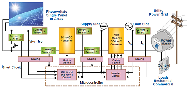
Figure 1. Current sensors are needed throughout grid-tied systems for control of the converters and inverters, optimization of power extraction from solar panels, and fault detection for safety.
PV systems
For a grid-tied photovoltaic system, the conversion of energy from solar panels is usually done in two stages. First, a DC / DC converter is used both to convert the voltage from the panel or array to something close to the grid voltage, as well as to maximize the power extracted from the panels. Then, an inverter is used to convert from DC to AC and sync it up with the grid. There is no standard or widely agreed upon topology for any of these stages or systems as a whole, as each conversion system is usually designed in their entirety by one manufacturer; each stage is designed and optimized to work most efficiently with the other stages in an attempt to yield the highest overall efficiency. Regardless of the system design, current sensors play an important role in the control of the different stages of conversion, directly impacting the efficiency and effectiveness of the system.
Conversion and MPPT
In any photovoltaic conversion system, maximum power point tracking (MPPT) is an important aspect, enabling maximum energy extraction from an array. The efficiency of MPPT algorithms is greatly impacted by the sensors used for feedback. The basis of MPPT is that at any given time the I-V curve of each solar panel indicates the optimum operating point, or maximum power point (MPP, see figure 2). However, it is also evident that the I-V curve and, subsequently, the MPP will change with both irradiance and temperature. It is the MPPT algorithm’s job to constantly search for the MPP.
There are many different MPPT algorithms; however, most operate by measuring power — either at the input or output of the DC/DC converter stage — and changing the operating point of the converter to move along the I-V curve to find the MPP. These algorithms all essentially perform some form of gradient ascent, estimating the slope of the current-(or voltage)-versus-power curve and using that to determine how to change the operating point. If the slope is positive, the operating point is increased; if negative, the operate point is decreased.
One of the most common algorithms is called perturb and observe. Here, the power from the solar panel or array is measured, the operating point is changed, and the power is measured again. If the power goes up, the operating point is moved in the same direction; if the power goes down, the operating point is moved in the opposite direction. This results in tracking of the MPP, though it also results in steady-state oscillation around the MPP. To minimize the steady-state oscillation the size of the steps can be reduced. However, the update rate must be increased to maintain the tracking speed.
Ultimately, the limiting factor in tracking efficiency will be the noise in the power measurement. This is because reducing the step size into the noise level of the power measurement will confuse the algorithm and lead to oscillation around the MPP. All “hill-climbing” algorithms, which includes perturb and observe, as well as incremental conductance, or ripple correlation control, to name a few, will be fundamentally limited by the noise in the power measurement sensors.
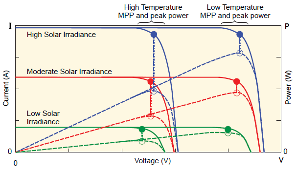
Figure 2. The graph above shows how I-V curves change with both irradiance and temperature. Subsequently, the maximum power point (MPP) will change, and the tracking algorithms must determine the new MPP.
For most MPPT applications, the bandwidth needed in a current sensor is in the hundreds of hertz, meaning one will typically filter or average the output of the sensor to decrease the noise and improve tracking efficiency. However, sensors are necessary if using ripple-correlation control, which uses the inherent input ripple of the DC / DC converter to measure the slope of the voltage vs. power curve.
The inverter stage
In a photovoltaic system, the DC/ DC converter stage is typically followed by an inverter stage, which ties the output of the system to the grid (see figure 1). This signal must be compliant with the utility system’s requirements, including proper synchronization to the grid and low total harmonic distortion (THD). Current sensors are needed in the systems’ control loops to ensure proper connection to the grid. The sensors must not only accurately measure both AC and DC currents, they must have high dynamic performance: very fast response times are needed to react quickly to any change in the grid, shutting off or disconnecting the system in the case of a short circuit (that is, ground fault) or loss of the grid connection (anti-islanding). The high output bandwidth is also needed to measure high-frequency AC currents and harmonics at different points in the system.
For inverters without a transformer or with a high-frequency transformer, sensors must exhibit low offset drift with temperature (high accuracy) so as to control the DC component in the AC current fed to the grid. Regulations differ from country to country for this electrical DC current limit, but generally it is small: on the order of tens to hundreds of milliamperes.
In a typical inverter configuration, there are a number of locations where a current sensor might be used (see figure 3). While one could use an expensive, high-precision current sensor, it is also possible to achieve high accuracy by using one or more economical current sensor ICs in conjunction with the microprocessor already necessary for the system. The on-board intelligence can be used to calibrate out offset error. For example, there will be periods of time where sensors 2 and 3 will have no current flowing through them. One can sample the output of the sensor ICs during those periods and use a moving average filter to generate an internal zero amperage output reference for that sensor IC, dramatically decreasing the offset drift, limited only by the noise and size of the averaging filter.
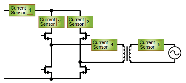
Figure 3. Multiple current sensors are seen in this diagram of a typical inverter configuration. For simplicity, filter components are not shown; however, they will usually be placed on either side of the transformer (if one is used at all), with designers often using the leakage inductance of the transformer as part of the filter.
For example, using a ACS710-6BB sampling at 20 kHz (with proper filtering to avoid anti-aliasing), and averaging 2,000 samples (over many different durations of zero current flowing through the sensor IC), can achieve a resolution of 1.5 mA to which the zero-current offset can be calibrated. When this calibrated sensor IC is put in series with another sensor IC, such as sensor 4, the relationship between the two can be determined, calibrating sensor 4 will provide a very low offset drift over temperature, allowing it to be used for sensing the DC component of the current fed to the grid. Ultimately, there are a number of similar techniques to calibrate current sensors dynamically in inverter applications depending on the particular topology and control scheme chosen that can lower overall system cost and provide significant space savings.
Based on an article originally published in Electronic Products, Hearst Business Communications, Inc., October 2013, pp. 40-43. Used with permission. For portions not copyrighted by original publisher, Copyright ©2013, Allegro MicroSystems, LLC.
The information contained in this document does not constitute any representation, warranty, assurance, guaranty, or inducement by Allegro to the customer with respect to the subject matter of this document. The information being provided does not guarantee that a process based on this information will be reliable, or that Allegro has explored all of the possible failure modes. It is the customer’s responsibility to do sufficient qualification testing of the final product to insure that it is reliable and meets all design requirements.