Crank Sensor IC for Stop-Start
Stop-start functionality allows automobiles to conserve fuel by shutting off the engine and restarting it at short intervals, such as at traffic stops. This feature requires advanced sensing technology to be efficient. This article describes start-stop operation and enabling Hall-effect integrated circuits, in particular the Allegro MicroSystems ATS694 and the previous generation ATS658, which are used in this application.
Introduction
Automobiles equipped with stop-start functionality save fuel by turning off the combustion engine when at a standstill, such as at a traffic light. The engine is restarted when the driver signals a resumption of driving, such as depressing the clutch or releasing the brake pedal. Publicized fuel economy improvements for stop-start systems are touted as up to five or ten percent. Furthermore, the reduction in fuel consumption through reduced engine idling time lessens the amount of released CO2, a benefit that is propelling extensive implementation in Europe, as automakers strive to meet tightening emissions standards.
Start-Stop Operation
The start-stop concept is not a new idea; several 1980’s vehicle models were released to production with this capability. Technological improvements in the last few decades have made stop-start operation a more reliable function. Moreover, the ability of modern vehicles to accomplish a restart of the engine quickly is critical to widespread consumer acceptance of this function.
Stop-start systems have a great cost-benefit when compared to hybrids that require parallel drive systems. The former rely heavily on existing components, requiring only a few equipment upgrades to achieve the fuel savings. Existing engine control units (ECUs) use inputs from sensors to dynamically adjust engine timing and fuel use to optimize performance. Additional ECU algorithms can be implemented to turn off the combustion engine when not needed. This requires inputs from already monitored systems, such as wheel speed, brake application, and battery status, which is necessary to ensure adequate power to restart the engine and to sustain electronics during the standstill period.

To achieve a restart of the engine, systems rely on a starter-generator or a heavier-duty starter motor (to withstand the increased usage). In addition, information from a crankshaft position sensor is utilized to reduce the time for a restart to just a fraction of a second. In a typical automotive combustion engine, an active sensor is used to monitor a special target on the crankshaft. In order for the ECU to determine the absolute crankshaft position, thereby providing piston position, the sensor must provide direction of target rotation. This direction detection capability enables the system to maintain synchronization throughout a standstill event, even in the presence of engine backlash. Without keeping synchronization, a restart event would likely take longer.
Sensing Technology
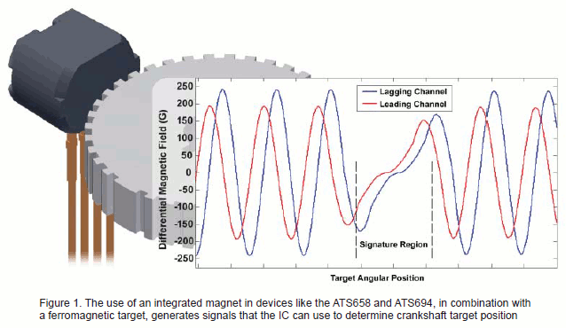
Allegro MicroSystems, LLC offers several automotive-grade, geartooth, Hall-effect integrated circuits (IC), specifically designed to meets the requirements for crankshaft speed and direction sensing for start-stop systems. These devices are built upon proven Hall technology, which provides digital contactless sensing of a ferromagnetic target. The IC family includes the ATS658 and ATS694, both of which are incorporated into a user-friendly, over-molded IC that integrates the Hall effect circuit with a rare earth magnet. The small package size and integrated magnetic system can be easily assembled and used in conjunction with a variety of target gears and installation air gaps. The combination of the sensor circuit with the back-biasing magnet in Allegro’s manufacturing facility ensures consistent device performance as each IC can be optimized to match a known magnetic circuit.
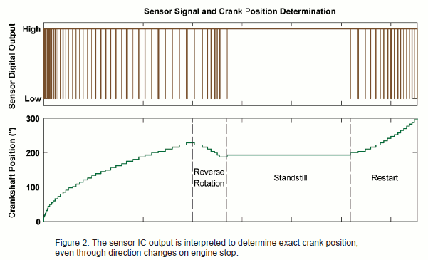
Although there are subtle differences between the two devices, both the ATS658 and the ATS694 contain three Hall elements used to generate two differential signals based on the magnetic stimulus produced by the rotation of the ferromagnetic target gear. The relative phase of the two signals is then used to determine the direction of target rotation. The sensor IC provides a digital voltage output signal where a short pulse is generated as the center of every target tooth passes by the device face. Two distinct output pulse widths differentiate whether the target is rotating in the forward or reverse direction. In this way, an engine control unit can determine both the speed of the target rotation, by looking at the period between consecutive pulses, and the direction of target rotation, by measuring the width of the output pulse.
Internal to these ICs, a number of patented analog and digital signal processing techniques are used. Advanced calibration techniques are used to provide optimal signal offset and amplitude. This calibration, combined with the digital tracking of the signal, results in accurate switching through the full range of installation air gap and target speed.
Unique signal tracking methods are also implemented to maintain signal integrity during long periods of standstill. Digital direction detection algorithms ensure that no erroneous output pulses will be generated during target direction changes, which can occur during engine stopping events. The combination of these techniques and algorithms allows these devices to track the absolute position of a crank target throughout an engine stopping event, ensuring that the ECU knows the exact position of the crankshaft (and therefore camshaft) and enabling a rapid restart.

296089-AN